Quartz and Thorium-Argon Lamp
Replacement
Printable Versions: Doc
PDF
last update: June 6, 2013
Notes:
- In order to change the quartz lamp or Th-Ar hollow cathode lamp,
the spectrograph must be off the telescope.
- If lamps should fail during a run, the f/5 Th-Ar and Quartz
lamps, located in the hub of the f/5 secondary, may be used. Note
that MAESTRO's slit acts like a pinhole, so your spectra will have
images of the f/5 lamp hub superimposed on the spectrum.
The f/5 Th-Ar lamps are dim, so exposure times will be long.
- Quartz lamps burn out quickly and are inexpensive. New
quartz lamps should be inserted before the start of every run.
Spare lamps are stored in a plastic box in the MAESTRO cabinet in the
common building of the MMT. At least once, the two quartz bulbs
burnt out simultaneously.
- The Th-Ar hollow cathode is a custom made item, with the thorium
lines enhanced, and costs $500. We have one spare, which is kept
in the MAESTRO cabinet in the common building of the MMT.
- We also have several other hollow cathodes containing
elements besides thorium, but none have as rich a spectrum as the
thorium-argon hollow cathode tube.
To Change Lamps:
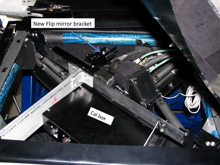
1. Remove the cover of the spectrograph which is on top of the
slit/shutter area. A slightly out-of-date photo is shown below.
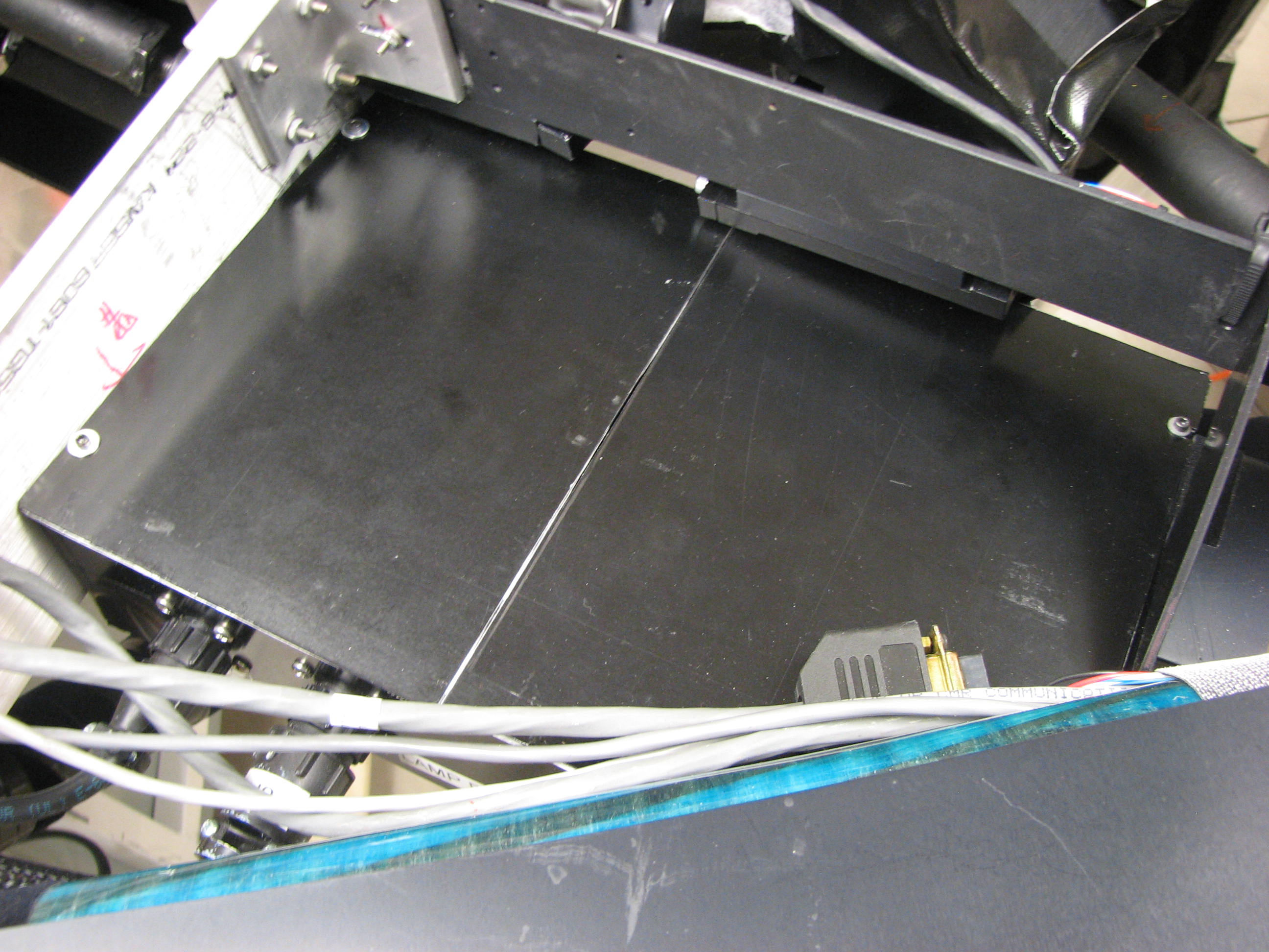
2. The cover of the comparison box is in two pieces which are
attached to the comparison box by small screws. Remove the screws
and remove the cover. Note that the cover on the left side is
easier to access. The lamps in their sockets are now easily
accessible.
3. Wear rubber gloves when handling any lamp; oil from your
fingers can have an adverse efffect on the lamps!
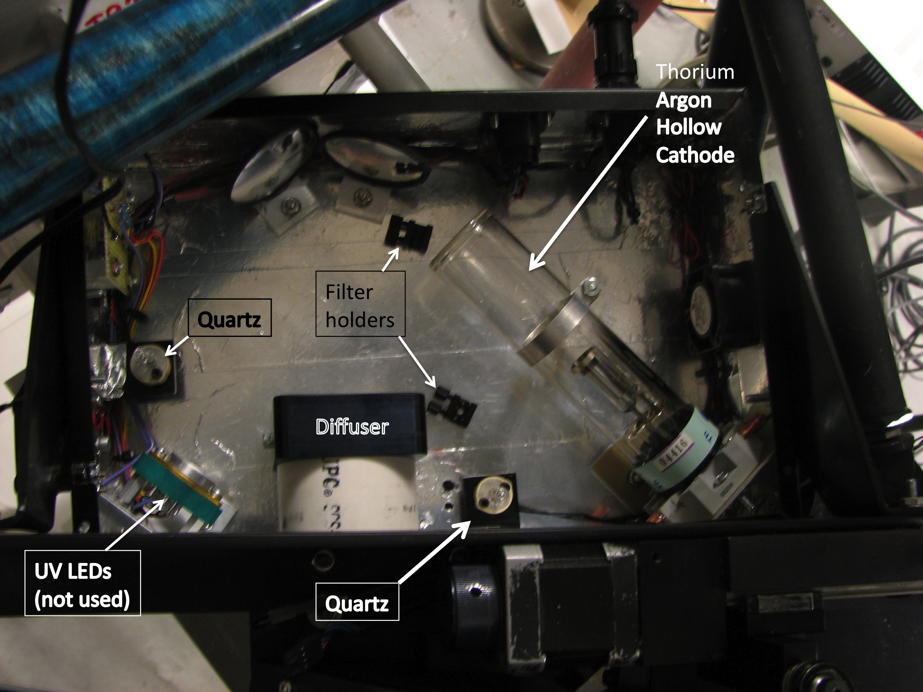
4. There are two quartz lamps, each with a different
color-balancing filter. To remove the bulbs, gently pull the
bulbs up.
5. There is one hollow cathode lamp socket containing the Th-Ar
lamp. A red-blocking filter is in place to make the argon lines
dimmer. To remove the lamp, unscrew the nut to loosen the ring
which supports the lamp halfway up the tube.
6. There is also a socket for UV LEDs which we intended to use
for flat-fielding. These are not functional at this time.
7. The reflective walls of the comparison box and the various
relay mirrors act as a poor person's integrating sphere. The lamp
light produced a spot on the diffuser, which is UV transmitting.
This spot is then relayed onto the focal plane, illuminating the slit
plate.
8. After you replace the two halves of the comparison box cover,
put a piece of black tape over the crack to keep it light tight.
The top cover of the spectrograph has been removed, showing the
comparison (flip) mirror, and the calibration lamp box.

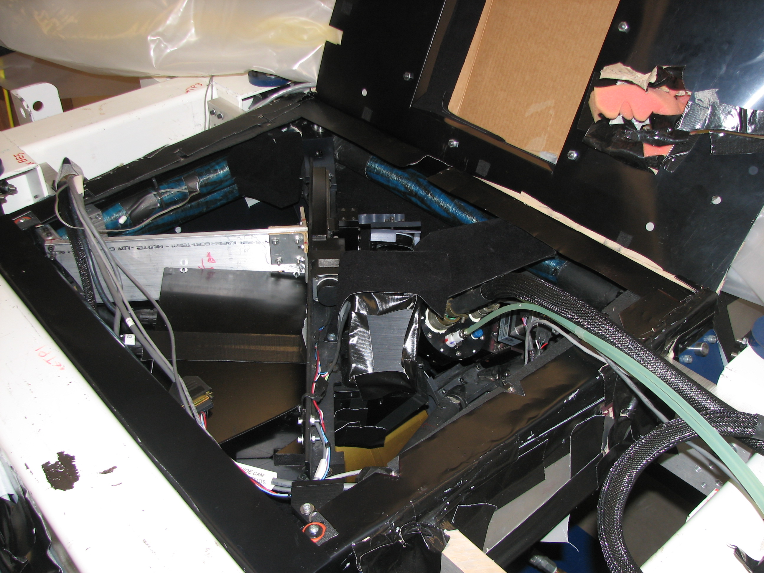
The comparison box area. The top cover
of the spectrograph has been rotated up, and can be seen in the upper
right hand part of the photograph.

The comparison box, showing the two halves of its cover:

The comparison box cover has been removed showing the inside of the
box. This is an old picture, taken during construction, and the
filters have not yet been installed. The picture was taken from
the grating side of the spectrograph, so the box appears upside down
compared to the pictures above.


