Polarization
Electro-Magnetic Waves
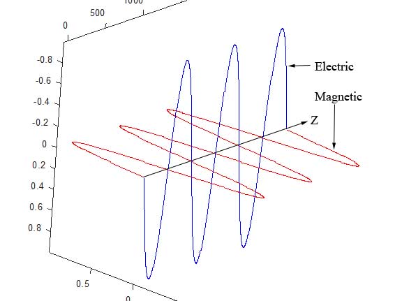
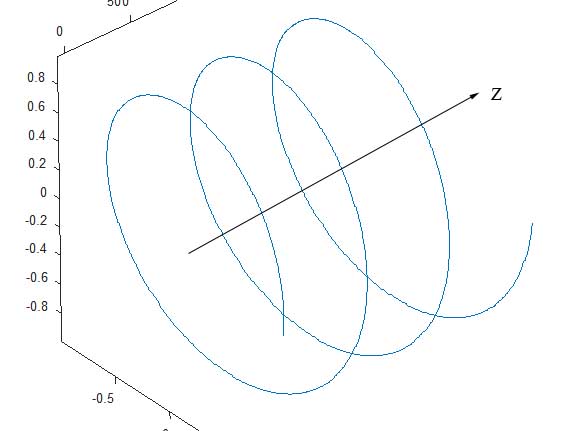
Since one of the ways of describing light propagation is a wave phenomenon, some very interesting effects are implied. Light can be described as a travelling transverse electro-magnetic (E-M) wave  , with the electric field and magnetic field perpendicular to one another. In almost all cases, the magnetic portion is implied and the electric field component is of interest. Typically, the orientation of the electric field is described by a pair of orthogonal vectors , say in the x̂ and ŷ directions, with ẑ being the direction of propagation. The figure below depicts the electromagnetic wave propagating in Z.
If the magnitude of the x̂-component (of the E field) is zero, then the light wave is said to be linearly polarized in the ŷ direction, and vice-versa. If both components are non-zero, and in phase then the light is linearly polarized at an angle of Tan-1(y/x).
Only rarely do natural light sources have anything but random polarization, but that doesn't mean that polarized light doesn't occur in nature. One of the principal methods for naturally occuring polarized light is via the process of reflection from a specular surface , such as from a lake. The Fresnel equations (named for Augustine-Jean Fresnel ) describe what percentage of light is reflected, as a function of incident angle, for the so-called s (from senkrecht, German for perpendicular) and p (parallel) polarization states. It should be noted that s and p are relative to the direction of propagation into a surface. The s component has the electric field vibration plane perpendicular to the plane containing the angle of incidence (the plane of incidence ), whereas the p component is parallel. For example, on a horizontal surface such as a lake, light incident angled from above has an s component that is horizontally polarized, where the verical polarization is the p component.
Fresnel Equations
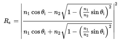
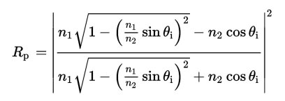
For non-magnetic media, with n1 being the index of refraction of the incident media and n2 the index of the second (refracted) media, and θi the angle of incidence from the surface normal , the reflectance for s- and p-components is given below. Brewster's Angle is a function of the two indices of refraction, θB = Tan-1(n2 / n1). Another important phenomenon is described by the Fresnel equations - that being total internal reflection (TIR) , which occurs if n1 > n2. This happens when the angle of incidence is greater than the critical angle, where θc = Sin-1(n2 / n1). The Fresnel equations can be stated as (the reflectance for s- and p-polarization states):
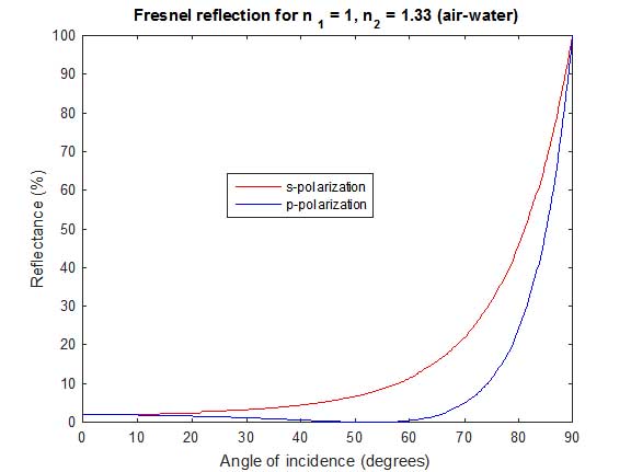
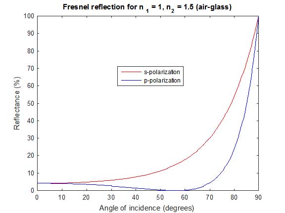
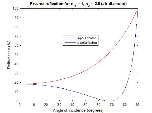
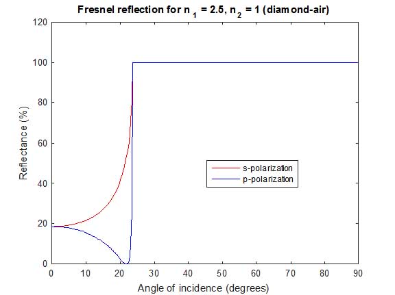
The s-component has a constantly increasing reflectivity as a function of incident angle, but the p-component actually decreases to a minimum value of zero at what is called Brewster's Angle, after which it rapidly increases. An easy way to remember how the Fresnel equations work is that "s skips, and p plunges", in other words, the p-component does not reflect at Brewster's Angle (it is transmitted), but the s-component is reflected. In this way, partial (or complete, at Brewster's Angle) polarization is naturally occurring.
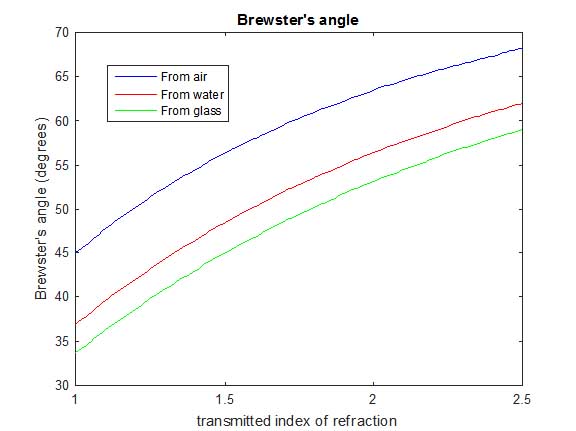
Plotting the reflection coefficients as a function of angle of incidence for less dense to more dense media, we see polarization by reflection, most strongly at Brewster's angle. The three sets of graphs are for air into: water, glass and diamond (n = 1.33, 1.5 and 2.5).
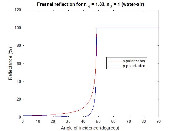
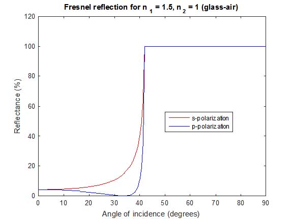
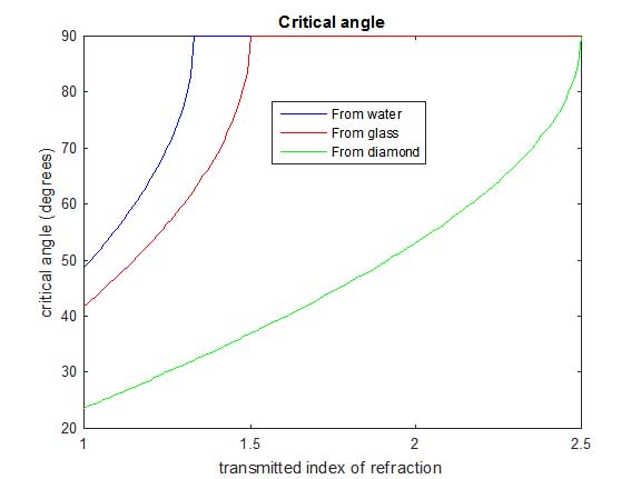
And if we reverse the incident and transmitted media, we see total internal reflection occurring at the critical angle.
The key points in the above graphs are:
- The reflectivity at normal incidence (0°) increases with increasing index.
- The reflectivity at normal incidence is always the same for p and s, since they lose their definition without a plane of incidence.
- Brewster's angle occurs at larger incident angles with increasing transmitted index.
- The difference in reflectivity increases with increasing index.
- Approaching 90° angle of incidence, the s-polarization state always has very high reflectivity.
- Approaching 90°, the p-state increases reflectivity very rapidly, especially with high index media.
- The critical angle decreases with increasing incident index.
What the above two graphs tell us is:
- Brewster's angle increases with increasing transmitted index, but is reduced by increasing incident index.
- There is no critical angle if the second index is greater than the incident index.
- The critical angle decreases with incident index, but increases with transmitted index.
The preceeding information shows why diamonds are cut at the angles they are, as well as why, with identical geometry, a diamond looks as it does compared to glass - total internal reflection is much more likely. They also are less brilliant if submerged in water or oil, for example, since there is less chance for TIR.
Polarization States
To summarize, light can be thought of as a pair of othogonal elecric field vectors, broken into these pairs depending on the angle of incidence to a surface. A different relationship to the surface changes the magnitudes (and perhaps identities) of the s- and p-polarization states. Depending on indices of refraction and incident angle, the light may become partially or completely polarized into one state. Travelling from a higher index material to a lower index creates the possiblity of total internal reflection.
So far, we have discussed materials which are non-magnetic, and do not absorb light. Things get a little trickier with metallic reflections, for example. With dielectrics , a constant phase shift occurs on reflection, but with metals, the phase shift is polarization dependent. Going back to the first depiction of the E-M fields, for a moment pretend that they are the orthogonal electric field components that when combined create linearly polarized light at 45°. This is because the two waves are in phase, meaning that they have zero field strength at the same moment (they come together on the Z-axis simultaneously).
Now imagine that one is shifted by some amount, say 90°. They are still orthogonal and have the same amplitude, but vector addition shows that as they propagate, the resultant electric field actually spirals around, as shown below. This is called circular polarization .
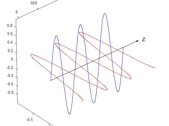
A phase shift other than 90° has other effects. A phase shift of 180° rotates the plane of polarization by 90° since instead of +/+, we now have +/-, or exactly out of phase (for one component). Other angles create elliptical polarization , which is the underlying polarization state for circular as well as linear. If the s and p amplitudes start out equal, but one is attenuated more than the other (see polarization by reflection), this rotates the plane (see vector addition). If there is also a phase shift, even by 90°, unequal amplitudes will manifest as elliptical polarization.
Polarization Modification
Reflections, either from dielectrics or metals, are not the only way to manipulate the polarization state. Certain materials, namely crystals and polymers, have molecular structures which are anisotropic , meaning that their properties (namely index of refraction) vary depening on orientation. A homogenous medium is the same everywhere, whereas an isotropic medium is the same from all directions. These are not equivalent! You can have a material that is completely uniform throughout it's volume, but yet has different properties depending on direction. Alternately, you can have a material that looks the same from all directions, but has localized internal inhomogeneities.
For example, a crystal may be entirely uniform, but the molecular stack up leads to a larger index of refraction for light that is vertically polarized than for horizontal polarization. The axis with the larger index is referred to as the slow axis and the lower index the fast axis. A material that exhibits this property of index anisotropy is called birefringent , meaning it has two indices of refraction. The difference in index is called the birefringence. Certain optical devices take advantage of this property of crystals or polymers. The birefringence multiplied by the thickness traversed is called the retardance of a device, since it retards, or slows, the light of one polarization state with respect to the other.
The most common retardation devices are called quarter-wave retarders (or quarter-wave plates) or half-wave retarders (half-wave plates). It doesn't take too much imagination to figure out that they introduce, respectively, 90° and 180° phase shifts (with 360° being a full-wave retarder, of course). A QWP is used to convert linear polarized light, at 45° to the fast and slow axes, to circularly polarized light, and vice versa. A HWP is used to rotate the state of polarization by twice the angle between the incident polarization and the fast axis.
While reading this, you are probably looking at vertically polarized light, from an LCD monitor, which is a polarization modifying device. Liquid crystals are often highly birefringent, and can be oriented with a small electric field, making them a good candidate for real-time polarization control. Depending on the specifics of the device, you may start with unpolarized light, which then gets polarized (losing half of the light in the process). The liquid crystal can either be oriented to essentially not effect it, or to rotate the plane of polarization by up to 90°. A second polarizer, generally at 90° to the first one, called an analyzer then lets some portion through, ranging from almost none (creating a black pixel) to almost all (a white pixel) with varying shades of grey in between.
Microscopy can utilize this property, with crossed polarizers creating a dark background. If a birefringent sample is placed between the crossed polarizers, the polarization state is altered, allowing some of the light to make it through the analyzer, making the subject visible, as seen below with potassium ferricyanide crystals altering the polarization state, allowing light to pass in that region.
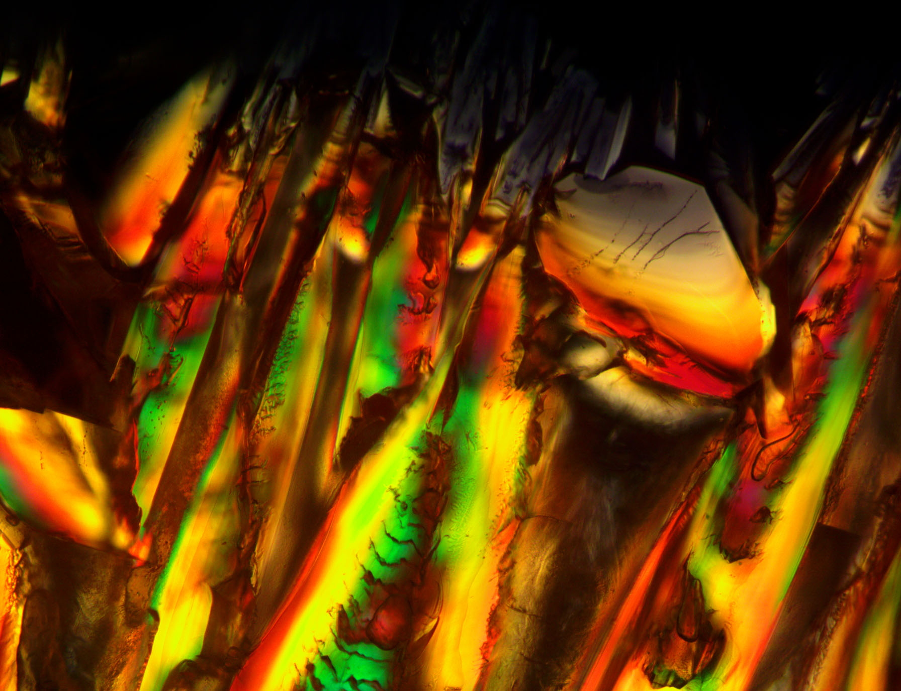
Retardance, as mentioned, is the birefringence times the thickness, so you may have for example 1 micron of retardance. At 500 nm wavelength light, this is two full waves, but at 400 nm light, it is 2.5 waves, and at 600 nm, it is 1.67 waves of retardance. Since different wavelengths see different phase shifts, some get rotated by 90°, making it through the analyzer, and some get 180°, being blocked. For (especially thick) samples, this can lead to vivid colors being represented in the field, as seen below for a thicker section of the potassium ferricyanide crystal. Rotating the polarizers (or specimen), or introducing a bias retardation, effects the visible colors in the image. Very thin specimens can exhibit a increase of contrast over plain crossed polarizers, but since the retardance is low, there isn't great variations in phase shifts between wavelengths, so colors are not produced, as seen above.
A device to measure retardance is called an ellipsometer and is fairly easy to implement, in its simplest form. They are most often seen as a reflection device, for measuring thin films or metals, but I personally am more familiar with the transmission type. All it really is composed of is a lamp and wavelength filter, a polarizer and analyzer (another polarizer that can be accurately rotated), and a photodetector. Your waveplate goes between polarizers, with the fast/slow axes at 45° to the input plane of polarization. By measuring the light that gets through the analyzer at 0° and 90° (180° and 270° are also typically measured for noise reduction, since they are theoretically the same as 0° and 90°). A simple formula computes the retardance... with a caveat. Since we are dealing with periodic functions, one cannot differentiate between 0° and 360°, for example.
This leads to my next point - when you purchase a QWP for example, there are several types. One of the variations is in the material, be it a natural crystal, such as mica or calcite, or a manufactured polymer. The next major point is if it is a zero-order retarder, which means that it has 0.25 waves of retardance, and not 10.25 waves, for example, which is a multiple-order retarder. They both convert the input linear light to circular, but as with the thick microscopic specimen, the multiple-order retarder does stranger things with light that isn't monochromatic (essentially one wavelength).
Even with zero-order retarders, there are "true" zero-order, which literally have the retardance advertised, generally by making them very thin (typically with polymers, rather than calcite for example). To make a thick zero-order retarder, they actually construct it from two, with very small difference in thickness. They take the thick one and align its fast axis with the slow axis of the thin one, which effectively subtracts the retardances, so they may have a 10.25 wave and a 10.0 wave that they cement together to get the 0.25 waves desired. The main drawback to this is that it makes it much more dependent on the field angle going through the device than with a thin zero-order retarder.
Double Refraction
Another potential effect with some crystals is called double refraction (see birefringence ) in which not only is the slow axis retarded from the fast, but the two polarization states actually get refracted differently, making them emerge angularly displaced (laterally sheared) from one another. This makes a double image with a thick crystal cut appropriately. With proper engineering, a very small lateral shear can be introduced, to produce two beams that once recombined, have the ability to convert small phase variations into visible intensity variations. This is the principle behind differential interference contrast (DIC) microscopy. The device used is either a Wollaston or Nomarski prism to create the shear.
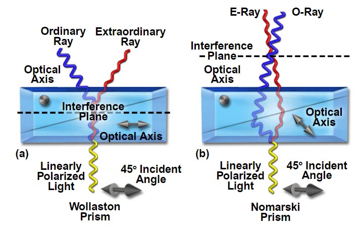
The above image is taken directly from Nikon's Microscopy U.
While the mathematics to describe polarization effects is fairly straightforward trigonometry, it can get rather cumbersome in short order. To help with the "bookkeeping", matrix methods are often employed. In a nutshell, the polarization state of light is contained in a 1x2 vector and a 2x2 matrix operates on it, representing an optical element. This is called Jones calculus , and cannot represent partially polarized light. A further refinement, which can deal with partial polarization and coherence uses 1x4 Stoke's vectors to define the state of the light and 4x4 Mueller matrices to modify it (via a device or reflection, for example).
Polarizers
There are several types of polarizers, both linear and circular. The basic function is to convert incident light into a known polarization state, by crystals, polymers or polarization by reflection.
Linear Polarizers
The most common type of linear polarizers are the polymer sheet variety. These are made by stretching polyvinyl alchohol (PVA) to stretch the polymer in a specific direction. Iodine is then introduced, creating an anisotropy wherein the incident E-M wave has a resonance in the stretch direction, interacting with the free electrons in the idodine. Light is only transmitted with the E vector perpendicular to the stretch direction.
For (generally) long wavelengths, such as microwaves and infrared, a wire-grid polarizer can be used, which is similar in function to the anisotropic iodine setup mentioned above.
Certain arrangments of crystals offer preferred polarization transmission, such as the Glan-Thompson prism .
Malus's law tells us that the transmissivity of two linear polarizers with the second rotated an angle A from the first is cos2(A). For ideal devices, 100% is transmitted for aligned polarizers (with the input polarization aligned), and 0% for crossed polarizers (90°).
Circular Polarizers
Circular polarizers are of two basic types: ones that inherently create circular polarization and ones that first convert to linear and then to circular via an attached QWP.
Circular polarizers are used in photography because the modern auto-focus sensors do not like linear polarization at a random angle, so the solution is to block out the offending linear polarization by orienting the filter 90° from it and then convert the transmitted light into circular. Microscope filters are often circular, as well, but used backwards, creating linear polarization. I think this is in order to ensure that some light makes it through the rotatable linear polarizer, even if the input is already linearly polarized.
Last updated February 10, 2021. If you arrived via an external link, please visit the homepage  for navigation!