Tour of MAESTRO
Last update: June 10, 2013
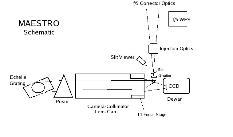
MAESTRO is located at the f/5 Cassegrain focus, attached to the
instrument rotator. It uses the f/5 secondary, spectroscopic corrector
optics, and atmospheric dispersion prism built by Dan Fabricant's group
at SAO. The light from the telescope enters the spectrograph through a
small glued doublet (we call the injection optics) which transforms the
f/5
beam to f/3. It then passes through the slit, and is turned 90 degrees
by a small folding flat mirror. The collimator consists of a set of 6
lenses, and is used in double pass. The overall design is patterned
after the MIKE echelle at the Magellan telescope.
The light passes through 3 singlets (BSM51Y, fused silica, PBM18Y) and
then a glued triplet of BSM51Y -CaFl-BSM51Y. BSM51Y and PBM18Y are
i-Line glasses made by Ohara, which have high ultraviolet transmission.
The light then passes through the fused silica prism, the echelle
grating, then back through the triplet and 3 singlets, and through a
field flattener which is the dewar window, made of fused silica. The
CCD is tilted slightly. The first of the 6 lenses (L1) is movable, for
focus control. The collimated beam passes through a prism
cross-disperser, and then is reflected off a custom ruled echelle
grating.
The light then passes again through the cross-disperser prism, the lens
can, and onto the CCD detector. The dewar window acts as a field
flattener. The CCD is tilted slightly to improve optical performance. A
schematic of the optical lay-out is shown below.
CCD DETECTOR
The detector is a 4kx4k back-illuminated CCD which was thinned and AR
coated to optimize UV sensitivity, by Mike Lesser's group at the
University of Arizona Imaging Technology Lab (ITL). It is type JPL4096,
UA ITL serial number SN3464. The camera uses an ARC Gen-3 controller,
run by an on-board PC and the AZCAM data acquisition software.
The user controls the CCD via an IRAF/ICE interface running on a linux
box in the control room. The CCD has 15 micron pixels; one
arcsecond at the slit maps to 6.5 pixels on the detector. The readnoise
in the lab is 3.4 electrons RMS.
GRATING AND SPECTRAL FORMAT
The grating was custom ruled by Richardson Grating Labs, in order to
optimize the spectral format on the detector. It is a single plano
echelle grating of zerodur with aluminum overcoat, 204mmx408mm with 60
grooves/mm and a blaze angle of 64 degrees. The manufacturer
measured the quantum efficiency which, for a typical order, is shown
below.
OPTO-MECHANICAL DESIGN
Since the MMT does not have a Nasmyth platform, we mount MAESTRO at the
Cassegrain focus. As a result, we had to worry about minimizing
flecture from the changing gravity vector, while keeping the instrument
within the allowed weight limit (3000 pounds) for the instrument
roatator. The optics and detector are mounted in a light space frame
constructed out of carbon fiber tubes and honeycomb sandwich panels. To
keep costs low, we obtained the carbon fiber tubing used for boat oars,
which we stress tested to insure that they were strong enough for our
purposes, despite having a lower fiber density than tubing used in
industrial applications.
The honeycomb sandwich panels were donated by the Hexcel Composites of
Casa Grande, Arizona. The individual components were glued together
with JB weld with invar reinforcements at most joints. The panel edges
were sealed with carbon fiber tape which was glued on with JB weld.
Bolt holes were made by gluing pre-made plastic inserts.
TARGET ACQUISITION AND GUIDING
A Steward CCD Guider camera is used as a slit viewer, and enables the
target to be centered on the slit. It has a 512x1024 pixel CCD used in
frame transfer mode. More information is given at
http://www.itl.arizona.edu/ITLGuiders/index.html. Guiding is done
off-axis with the f/5 guider. Eventually, wave front
sensing will also be done without interrupting the observing sequence,
off-axis with the f/5 WFS camera.
The rest of the tour may be found HERE.